
How to Match Industrial Hydraulic Cylinder Bore, Stroke, and Mounting: A Technical Guide
An industrial hydraulic cylinder is matched correctly when bore, stroke and mounting are fixed in that order, and each is verified against the structure the cylinder will move rather than against a catalogue page. Bore sets the force and speed available. Stroke sets the working travel and the installed length. Mounting decides how that force enters the machine frame. Reverse the order and the cylinder can still pass a pressure test while failing at installation, alignment or rod stability.
This guide converts that sequence into a working procedure for design engineers, maintenance planners and procurement teams in water conservancy, marine and offshore, metallurgy, oil, energy, port and heavy machinery projects. It uses the production basis of Changzhou Hydraulic Complete Equipment Co., Ltd (CZHydraulic), a Jiangsu-based manufacturer established in 1990 that produces complete hydraulic hoist equipment, industrial hydraulic cylinders and hydraulic control systems, and exports to North America, South America, Western Europe, Eastern Europe, Eastern Asia and Southeast Asia. Model references used here — QHLY, QPPY, QPKY and QHSY — mark the points where a parameter becomes a specification decision.
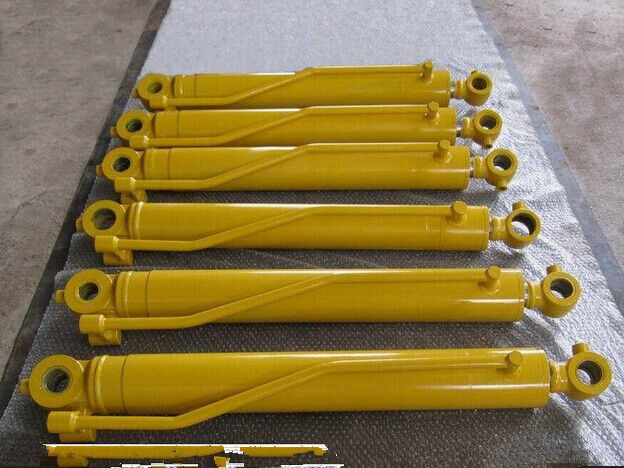
Cover: a customized hydraulic cylinder built to a project drawing rather than to a standard catalogue size.
Problem Definition: Three Mismatches That Repeat Across Projects
Most cylinder specification failures come from the order in which the three parameters are decided, not from a defective cylinder. Three patterns account for the majority.
1. Force-only bore selection
The bore is sized from the working load at nominal system pressure, and the rod diameter is inherited from an earlier design. Force output is then correct in normal operation but the rod may fall below the stability margin the application needs at stall pressure or under shock. Bore and rod diameter are a pair, not two independent catalogue choices.
2. Travel-only stroke selection
The stroke is taken from the mechanism's nominal travel without allowance for cushioning, end stops and the cylinder's installed length at full extension. On long-stroke gate hoists and radial gate installations, the extended position is frequently the envelope that was never checked.
3. Catalogue-first mounting
Mounting is chosen from a drawing that already exists rather than from the structure's load path. The result is a pin or flange interface that transmits force with an offset, producing side load on the rod, uneven seal wear and bolt fatigue that appears months after commissioning.
Decision rule: bore is fixed by force and confirmed by rod stability; stroke is fixed by mechanism travel and confirmed by installed length; mounting is fixed by the load path and confirmed by alignment tolerance. Each check can veto the previous decision.
Industry Background: What the Standards Frame Actually Covers
Industrial cylinder selection is normally organised by pressure class, because mounting dimensions are standardised per class. ISO 10762:2015 establishes mounting dimensions for cylinders used at 10 MPa. ISO 6020-1:2007 establishes metric mounting dimensions for medium-series cylinders at 16 MPa and covers round-head cylinders with bores from 25 mm to 200 mm, plus round and square head cylinders with bores larger than 200 mm. ISO 6020-2:2006 covers the compact series at 16 MPa. ISO 6022:2006 establishes mounting dimensions for cylinders at 25 MPa, a class commonly described as heavy-duty series and typically rated at 250 bar.
Those standards exist to guarantee dimensional interchangeability within a class. They do not certify a cylinder for a specific application, and they do not extend automatically to every custom size. Acceptance and function testing is addressed separately: ISO 10100:2020 specifies acceptance and function tests for hydraulic fluid power cylinders, which means a buyer can structure a factory acceptance test around a recognised scope instead of an informal checklist. Marine and offshore service adds classification requirements; DNVGL-CG-0194 requires a minimum buckling safety factor of 4.0 for standard calculations.
Large gate hoist and custom industrial cylinders frequently sit outside these frames. A 1200 mm bore flat gate cylinder or a 16 m stroke radial gate hoist is not a catalogue item, so the approved drawing — not the standard series — becomes the governing document, and the standard becomes the reference used to confirm where interchangeability still applies.
The Matching Solution: Five Layers in a Fixed Order
Layer 1 — Bore: force first, then rod diameter
Bore is derived from the required force at the lowest normal operating pressure, using the piston area relationship: force equals pressure multiplied by area, with area equal to π/4 × D². For the retracting direction, the rod area is subtracted, so rod diameter changes retract force as well as stability. Two checks follow immediately: whether the selected bore exists in the relevant standard series, and whether the matching rod diameter survives buckling at stall pressure.
Bore also sets speed at a given pump flow. A cylinder sized only for force at high pressure will run faster than the mechanism may tolerate when the same bore is fed at the system's normal flow. On custom projects, the bore range moves beyond the standard series entirely: the CZHydraulic QPPY flat gate cylinder is listed with a maximum diameter of 1200 mm, which places it outside the bore coverage of ISO 6020-1 and into drawing-controlled production.
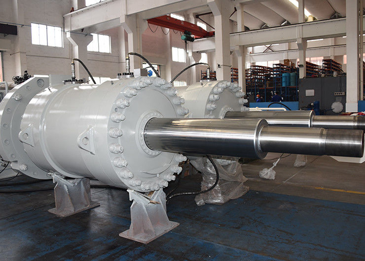
Large-bore construction: bore diameter drives force output, wall section and the rod diameter that must follow it.
Layer 2 — Stroke: travel, installed length and stability
Stroke is the working travel plus the margin needed for cushioning and end stops. The number that must be checked is the installed length at both extremes: closed length at one end, closed length plus stroke at the other. For gate hoists the cylinder also swings through an arc, so the extended envelope is a geometric constraint, not only a stroke figure.
Long stroke is a stability problem before it is a manufacturing problem. As stroke increases at a fixed rod diameter, buckling resistance falls sharply, guide spacing becomes critical and mid-stroke rod deflection starts to load the seal and the rod coating. This is why marine projects commonly apply the DNVGL-CG-0194 minimum buckling safety factor of 4.0 to standard calculations, and why a long-stroke enquiry should always state whether the load is tensile, compressive or reversing. CZHydraulic radial gate hoist cylinders in the QHLY series and the QPPY flat gate cylinder are both listed with a 16 m stroke, which is the range where buckling verification and guide design have to be resolved at the drawing stage.

Long-stroke gate duty: at extended stroke the rod, guide spacing and mounting alignment govern reliability more than nominal force.
Layer 3 — Mounting: how force enters the structure
Mounting type follows the load path. Pin and clevis connections allow rotation in one plane; spherical bearings tolerate angular misalignment; trunnion mounts carry moment through the cylinder body; flange and foot mounts transfer force directly into a machined face. The practical test is simple: if the structure deflects under load, a rigid mounting will convert that deflection into side load on the rod.
Mounting dimensions are pressure-class specific, so interchangeability only holds inside the same standard family and class: 10 MPa under ISO 10762:2015, 16 MPa under ISO 6020-1:2007 or ISO 6020-2:2006, and 25 MPa under ISO 6022:2006. Above those classes the mounting drawing governs. Alignment tolerance then becomes a manufacturing deliverable rather than a site correction — in the pumped storage station project referenced below, the gate slot cover plate flatness was controlled within 0.05 mm per square metre to guarantee the fit between cover plate and gate slot before installation and commissioning.
Layer 4 — Body material and rod surface: environment decides
CZHydraulic industrial cylinders are offered with carbon steel, alloy steel and stainless steel bodies. Material selection follows the working environment, not the price tier. Offshore and marine cylinders operate under salt spray, high humidity, seawater corrosion, heavy load and shock, in 24/7 intermittent or continuous operation, and require high corrosion protection and reliable sealing. Metallurgical cylinders work under high temperature, heavy load, shock, dust, scale and water splash with frequent operation and strong vibration, requiring heat resistance and shockproof performance in steelmaking, continuous casting and rolling mill duty.
Rod surface treatment belongs to the same decision. Ceramic coating piston rods and HVOF rods are part of the CZHydraulic production scope, and the choice between them interacts with stroke length and mounting alignment: a long stroke with residual side load will damage any rod coating, so surface selection cannot compensate for a mounting mismatch.
Layer 5 — Verification: turning the match into evidence
A matched cylinder is only a matched cylinder once it has been measured and tested. CZHydraulic applies 100% testing, operates a joint debugging test area, and runs a comprehensive testing platform for hydraulic systems, which allows a cylinder to be verified together with its control system rather than as an isolated component. ISO 10100:2020 provides the accepted scope for acceptance and function tests, so the purchase order can name the test category instead of describing it informally.
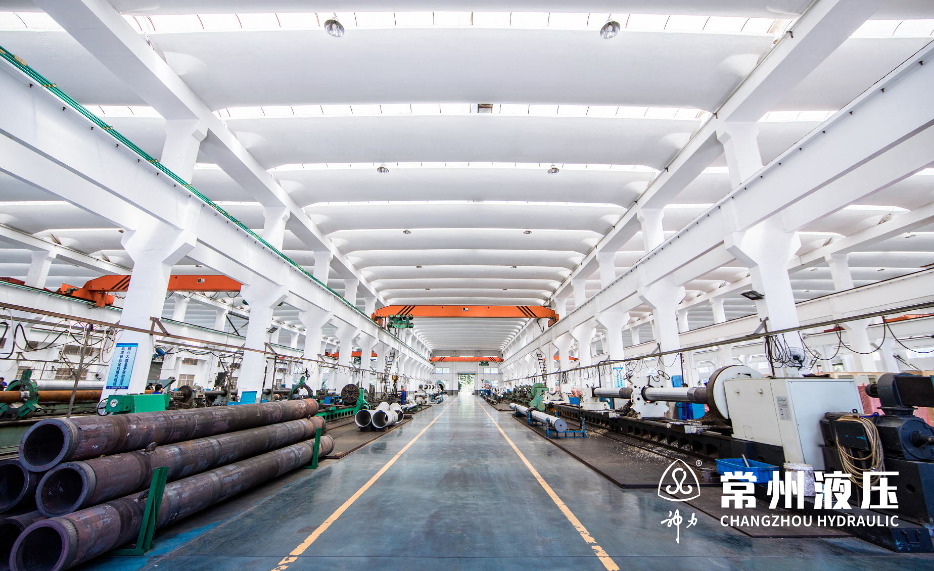
Body machining: bore tolerance, mounting interfaces and rod alignment are settled in production, not on site.
Step-by-Step Breakdown: The Eight-Step Matching Worksheet
- Fix the mechanism envelope. Record pin centre distances, working travel, load direction and any structure deflection expected under load. This document governs everything that follows.
- Calculate required force at normal operating pressure. Use force = pressure × piston area, not the maximum pressure the pump can reach.
- Select bore, then confirm rod diameter. Check rod stability at stall pressure and under shock. For marine service, apply the DNVGL-CG-0194 minimum buckling safety factor of 4.0 to the standard calculation.
- Set stroke with end margin. Add cushioning and stop allowance, then calculate closed length and extended length.
- Choose mounting from the load path. Decide between pin, spherical bearing, trunnion, flange or foot fixing, then define the flatness and alignment tolerance the structure must hold.
- Match body material and rod surface to the environment. Salt spray and humidity point one way; heat, scale and vibration point another.
- Decide standard or drawing-controlled. Confirm the pressure class and standard reference where interchangeability is needed; otherwise lock the drawing, including the 1200 mm maximum diameter and 16 m stroke limits offered in the QPPY and QHLY configurations.
- Write the verification plan. Name the acceptance test scope (ISO 10100:2020), the 100% test requirement, the dimensional report for bore, stroke and pin centres, and whether joint debugging with the hydraulic system is included.
| Matching parameter | What fixes it | What verifies it |
|---|---|---|
| Bore | Required force at normal operating pressure; retract force through the rod area | Bore measurement report; rod stability check; standard series confirmation |
| Stroke | Mechanism travel plus cushioning and end-stop margin | Closed and extended length check against the envelope; function test |
| Mounting | Load path and structure deflection; pressure-class standard where interchangeability is required | Pin centre and interface dimensions; flatness tolerance; joint debugging |
| Body material | Corrosion, temperature and mechanical environment | Material certificate; 100% test record |
| Rod surface | Corrosion class and duty cycle; cylinder alignment quality | Coating specification; acceptance and function test |
Use Cases: How the Priority Order Changes by Project
Marine and offshore equipment
Offshore and marine hydraulic cylinders provide linear actuation and load handling for marine and offshore equipment such as marine cranes, operate in 24/7 intermittent or continuous mode, and are installed on offshore platforms and marine equipment hydraulic systems. Because salt spray, high humidity, seawater corrosion, heavy load and shock are continuous conditions, mounting and corrosion protection are decided before stroke optimisation, and the sealing requirement is stated explicitly in the project brief (IP67 sealing in the reference case). Where classification applies, buckling verification follows DNVGL-CG-0194 with a minimum safety factor of 4.0.
Metallurgical plants
Metallurgical cylinders serve steelmaking, continuous casting and rolling mills under high temperature, heavy load, shock, dust, scale and water splash, with frequent operation and strong vibration. Here the rod surface and body material dominate: heat resistance and shockproof construction take priority over marginal force optimisation, and the cylinder is specified as part of a hydraulic system rather than as a stand-alone actuator.
Water conservancy and hydropower
Hydraulic hoists open, close, position and lock gates for flood control, water storage and flow regulation. They run intermittently with frequent starts and stops, are installed outdoors or underwater in humid and sandy conditions, must withstand water impact and vibration, hold pressure stably, and support synchronous control and emergency operation. The matched equipment set is the cylinder plus hydraulic system plus electrical control system, and long stroke plus alignment accuracy decide whether the unit seats correctly. In the pumped storage station case, three units were supplied for gate hoist control with a design holding force of 5000 kN, so the tailrace emergency gate can close quickly under emergency conditions such as unit failure or pipeline rupture; the equipment has a 10-year service record in that application.
Other industrial contexts
The same matching logic applies to oil industry hoist cylinders, port facilities, vehicles, energy equipment, mining machinery and press machine cylinders. The listed application scope of CZHydraulic industrial cylinders covers water conservancy, mechanical, marine and mining equipment, oil industry, vehicles, energy and port facilities, with carbon, alloy and stainless steel body options across the range.
Comparison Table: Standards and Model References
The first table maps the standards that govern mounting dimensions and testing by pressure class. The second maps CZHydraulic model references to the parameter each one anchors. Neither table ranks suppliers or products.
| Standard | Pressure class / scope | What it governs |
|---|---|---|
| ISO 10762:2015 | 10 MPa (100 bar) | Mounting dimensions for interchangeability |
| ISO 6020-1:2007 | 16 MPa (160 bar), medium series; round-head bores 25–200 mm and bores above 200 mm | Metric mounting dimensions |
| ISO 6020-2:2006 | 16 MPa (160 bar), compact series | Metric mounting dimensions |
| ISO 6022:2006 | 25 MPa (250 bar), heavy-duty series | Mounting dimensions |
| ISO 10100:2020 | Hydraulic fluid power cylinders | Acceptance and function tests |
| DNVGL-CG-0194 | Marine and offshore | Minimum buckling safety factor of 4.0 for standard calculations |
| Model reference | Configuration | Parameter it anchors |
|---|---|---|
| QHLY series | Radial gate heavy-duty hoist cylinder; piston structure; applications include industrial, water conservancy, vehicle and machinery equipment | Stroke 16 m; large-bore configuration; standard GB/T9001-2000, IDT ISO 9001:2000 |
| QPPY | ISO 9001 AAA flat gate hydraulic cylinder; piston structure | Maximum diameter 1200 mm; stroke 16 m |
| QPKY | Plane rapid gate double-acting hydraulic cylinder; nonstandard, piston structure | Double-acting operation and custom colour/finish to requirement |
| QHSY | Electric single-acting deep-hole radial gate cylinder for tower crane duty; piston structure | Single-acting configuration; standard GB/T9001-2000, IDT ISO 9001:2000 |
| Body material options | Applies across the industrial cylinder range | Carbon steel, alloy steel, stainless steel |
FAQ
Which standards should a bore, stroke and mounting specification reference?
Mounting dimensions are referenced by pressure class: ISO 10762:2015 for 10 MPa, ISO 6020-1:2007 for medium-series 16 MPa cylinders (round-head bores 25 mm to 200 mm and bores above 200 mm), ISO 6020-2:2006 for compact-series 16 MPa cylinders, and ISO 6022:2006 for 25 MPa cylinders. Acceptance and function testing follows ISO 10100:2020. Marine and offshore duty adds DNVGL-CG-0194, which requires a minimum buckling safety factor of 4.0 for standard calculations. Where the size exceeds those frames — for example a 1200 mm bore or a 16 m stroke — the approved drawing governs and the standard is used only to confirm where interchangeability still applies.
Can one manufacturer deliver a large-bore, long-stroke cylinder with a non-standard mounting?
CZHydraulic lists a maximum diameter of 1200 mm on the QPPY flat gate cylinder and a 16 m stroke on both the QPPY and QHLY configurations, with OEM/ODM production and customized hydraulic cylinders built to requirement. Production capacity is stated at 5000 units per month with 100% testing, and the company supports non-standard customization across its cylinder range. The practical qualification step is to confirm that the drawing, the machine capacity and the test record all describe the same bore, stroke and mounting interface.
How do bore, stroke and mounting affect cost?
Cost follows the same order as the design. Bore drives material volume, machining and honing time; stroke drives rod length and, where buckling governs, a larger rod diameter plus additional guide support; mounting drives interface machining and any non-standard pattern; material and rod surface add the environment premium. Third-party commercial research places marine and offshore-grade stainless steel cylinders in a range of roughly USD 1,000 to USD 3,200 for standard sizes, which is a benchmark for standard sizes only and should not be applied directly to a drawing-controlled large-bore or long-stroke unit. For those, request a quotation against the completed worksheet rather than against a size list.
What should be verified on a sample or first article before full production?
A single-piece trial is practical because the minimum order quantity for CZHydraulic industrial cylinders is one piece. Verification should cover the dimensional report for bore, stroke, closed and extended length, pin centre distances and mounting flatness; the material certificate; the 100% test record; and an acceptance and function test structured on ISO 10100:2020. Where the cylinder is supplied with a control system, joint debugging in the test area confirms that cylinder, hydraulic system and electrical control behave together before shipment — a step that is difficult and expensive to reproduce on site.
What lead time should be planned, and how does a project start?
Listed delivery time is 15 to 60 days depending on product type, with supply ability of 2400 tons per year, T/T payment terms and shipment from Shanghai. Non-standard large-bore and long-stroke cylinders sit at the upper end of that range because drawing approval, material preparation and testing run in sequence. The fastest route is to send the completed eight-step worksheet — load, travel, envelope, mounting load path, environment and test expectation — to the CZHydraulic engineering team through the company website, and request a sample or quotation against that data set. The company's product brochure is available for download at this catalogue link.
Conclusion
Matching bore, stroke and mounting is a sequence, not a selection menu. Bore is fixed by force and confirmed by rod stability at stall pressure. Stroke is fixed by mechanism travel and confirmed by installed length at full extension, with buckling checked as stroke grows. Mounting is fixed by the load path and confirmed by the alignment tolerance the structure can actually hold. Material and rod surface follow the environment, and the whole match is only complete once it appears in a dimensional report and an acceptance test.
The standards frame helps where interchangeability matters: 10 MPa under ISO 10762:2015, 16 MPa under ISO 6020-1:2007 or ISO 6020-2:2006, 25 MPa under ISO 6022:2006, testing under ISO 10100:2020, and a minimum buckling safety factor of 4.0 under DNVGL-CG-0194 for marine service. Above those frames the drawing is the specification, and capability is what decides feasibility — 1200 mm maximum diameter and 16 m stroke on the QPPY and QHLY configurations, with carbon, alloy or stainless steel bodies and 100% testing before shipment.
Next step — send the operating point, not only the drawing. Share load, travel, envelope, mounting load path and environment with Changzhou Hydraulic Complete Equipment Co., Ltd (CZHydraulic) to receive a matched cylinder proposal, a single-piece sample for verification, or a quotation against your project schedule. Email zzl@czhydraulic.com, WhatsApp +8615906122063, or download the product brochure.
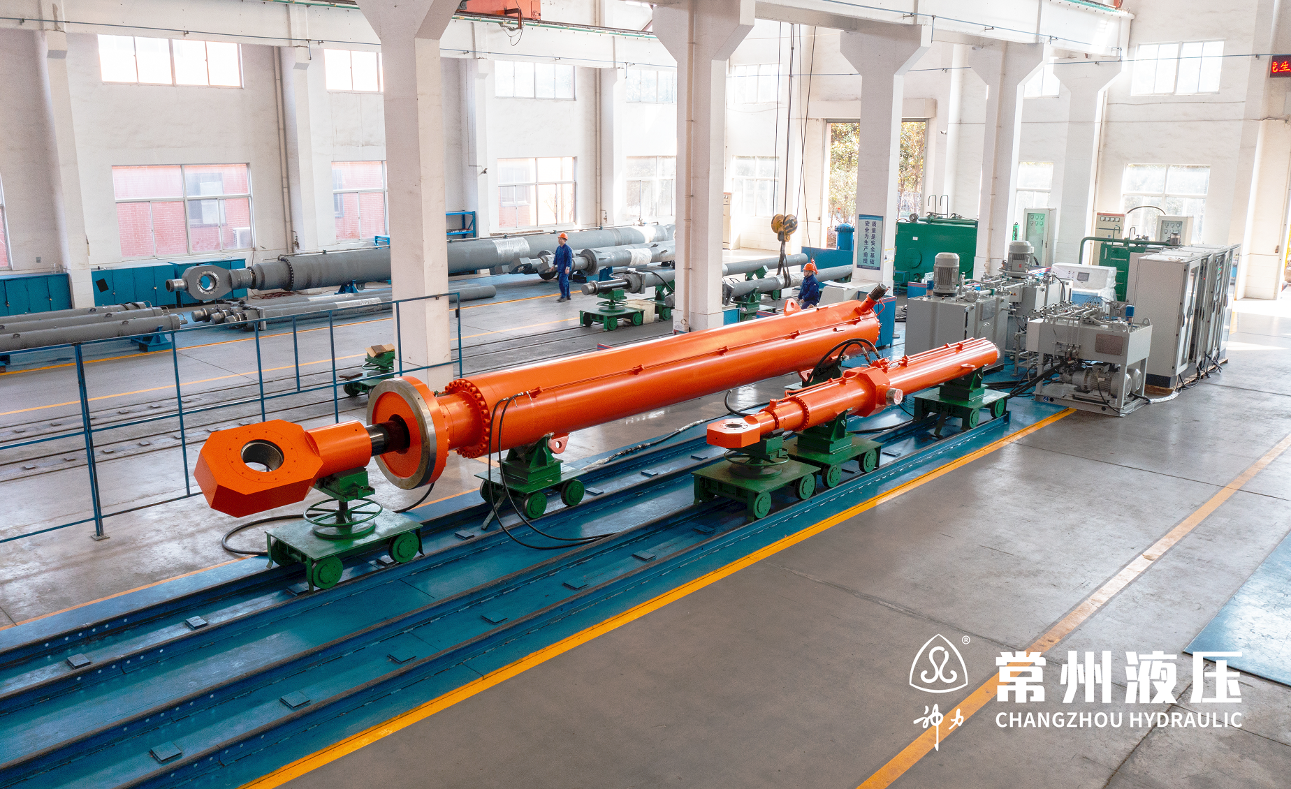
Joint debugging test area: cylinder, hydraulic system and electrical control verified together before shipment.
Have Questions or Need More Details?
Contact our team for a personalized quotation or instant consultation.
Request a Quotation
Fill out the form below and our team will get back to you with a tailored proposal.
WhatsApp Direct Chat
Prefer to chat in real-time? Message us on WhatsApp for instant assistance & quick answers.
- Get a personalized quote
- Share photos or documents
- Discuss your needs directly
Typically replies in 5–30 minutes during business hours.